


Position the pump with mounting bracket in place making sure that the pump is close enough to the boot wall to avoid the mounting bolt hole from fouling the chassis leg underneath but far away enough to allow clearance for the hydraulic pipes.

When happy, mark the location of the mounting bracket onto the boot floor.

Remove the pump and remove the mounting bracket from the pump. Position the bracket on the boot floor in the location marked out.

Mark and drill the first mounting bolt hole as shown.

Reposition the bracket and secure in place with a nut and bolt. use the bracket as a drill guide to drill the second hole. Then bolt in place. If you have sound deadening material stuck to the boot floor in this location as I have in the above pictures, then you have two choices. You can either cut away the sound deadening as required or pack underneath the rest of the mounts with rubber spacers as I have. You may need to position more packing under the front and rear rubber feet attached to the pumps frame.

Pump mounted in position.

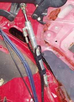
With the pump installed it's time to replace the roofs gas struts with the hydraulic rams.

The operating rams fit in the same location as the original gas struts but there mounting pins are different.
The original gas struts use ball joint mounts exactly the same as those used for the boot lid gas struts.
The hydraulic rams of the power roof however use pins and retaining clips.
It is worth making sure you use these clips as opposed to using bolts as you will get a slack fit with bolts which will soon result in ova-ling of the rams mounting holes and will also reduce the effective stroke of the ram as it takes up the slack.

The pins simply screw into the roof mechanism frame and the cars shell in the same manner as the ball joint mounts.

The longer pins are fitted to the shell at the base of the rams and the shorter pins are fitted to the roof frame.
Before the rams as offered into position, the hydraulic hoses need to be attached. They should then be taped to the ram body to stop them from snagging and migrating from position once installed.To make life easier later on, it is a good idea to identify each pipe at the pump end at this stage to make final connection to the pump easier. The hoses positioning and routing is down to personal preference. My choice of routing deviated slightly from the diagram in the Haynes manual but has worked well enough for me. I elected to tape the hoses to my rams in such a way as they both exited pointing downwards.

The Rams can then be slid onto there respective mounting pins and secured with the retaining clips. Be sure to make sure that the top hose connection on each ram is pointing inwards and towards the rear of the car. Otherwise the connections will foul on the interior trim panel or chafe any wiring you may wish to route through that area.

The next job is to route the hydraulic hoses under the rear bench seat and through to the pump in the boot. The best way to explain this is to simply show you the pictures of my layout. Just be careful to avoid sharp bends and protect the hoses from sharp panel edges that could cause chaffing.

The hoses have been secured to the shell with black tape. They have also been taped together to help keep them located. When under pressure the hoses don't appear to move a great deal anyway.

The pipes can then be attached to the pump. This is where your carefull labeling from earlier comes into play. The connection is quite simple. The pump has a 'T' piece on each side of the pump body. One 'T' piece supplys pressure to open the roof, the other supplys pressure to close the roof. It does not matter which side you use for which so long as you attach both rams top hoses to one 'T' piece and both rams bottom hoses to the other 'T' piece.

If you are using a manual roof frame as I have done, then the roof frame mechanism latches that hold the roof in the open position must be removed. This is achieved by simply drilling off the ends of the pivots that the latches are mounted to and removing the latches.

If you have the correct loom for the system then you'll have to figure this bit out for yourself as I didn't get one with my system. I had to make my own. I found an alleged copy of the Ford wiring diagram for the power roof but decided that it was way too over complicated for my needs so I devised my own system. The bonus with my system is that you don't need to have the ignition switched on to activate the roof so if your car is parked outside with the roof down and a freak shower comes along, you don't have to go fumbling around for keys before you can close the roof!
The 12 volt supplies come straight from the battery with inline fuses rated at 5 amps to the switch and 20 amps for the main power to the pump. Use suitably rated cable at a higher rating to the fuses to allow for current drain over the length of the cable

The relays are mounted by the pump rather than being hidden away.

The thermal cut-out is also located by the pump.
The switch is normally mounted on the centre console on the passenger side of the gear stick.

If you don't have the correct boot trim panel for the pump then you will have to cut a section out of your existing trim panel in order for it to fit around the pump. This is largely done by trial and error but you should end up with something like this.

Which when installed should give adequate clearance for the pump and cooling.

With all the electrics installed, you should end up with something along the lines of this.


Made with
WYSIWYG HTML Editor